- 您现在的位置:买卖IC网 > Sheet目录337 > LT3519EMS-2#PBF (Linear Technology)IC LED DRVR HP CONST CURR 16MSOP
LT3519/LT3519-1/LT3519-2
APPLICATIONS INFORMATION
L ( μH ) = BUCK
D ? ( V IN – V LED ) ? μH ? A ? MHz ?
f OSC (MHz) ? 0.15A ?
V
?
D BUCK = LED
L ( ) =
D BOOST ? V IN ? μH ? A ? MHz ?
( V LED – V IN )
V LED
Inductor Selection
The inductor used with the LT3519/LT3519-1/LT3519-2
should have a saturation current rating of 1A or greater.
For buck mode LED drivers, the inductor value should be
chosen to give a ripple current 150mA or more. In the
buck mode, the inductor value can be estimated using
the formula:
? ?
V
V IN
V LED is the voltage across the LED string, V IN is the input
voltage to the converter, and f OSC is the switching frequency.
In the boost con?guration, the inductor can be estimated
using the formula:
μH ? ?
f OSC (MHz) ? 0.15A ? V ?
D BOOST =
ESL and have an adequate ripple current rating. A 2.2μF
ceramic type capacitor is usually suf?cient for LT3519
(400kHz version). A capacitor of proportionately less
value for LT3519-1/LT3519-2 (higher frequency version)
can be used.
Output Capacitor Selection
The selection of output capacitor depends on the load
and converter con?guration, i.e., step-up or step-down
and the operating frequency. For LED applications, the
equivalent resistance of the LED is typically low, and the
output ?lter capacitor should be sized to attenuate the
current ripple.
To achieve the same LED ripple current, the required ?lter
capacitor value is larger in the boost and buck-boost mode
applications than that in the buck mode applications. Lower
operating frequencies will require proportionately higher
capacitor values. For LED buck mode applications, a 1μF
ceramic capacitor is usually suf?cient. For the LED boost
and buck-boost mode applications, a 2.2μF ceramic ca-
pacitor is usually suf?cient. Very high performance PWM
dimming applications may require a larger capacitor value
to support the LED voltage during PWM transitions.
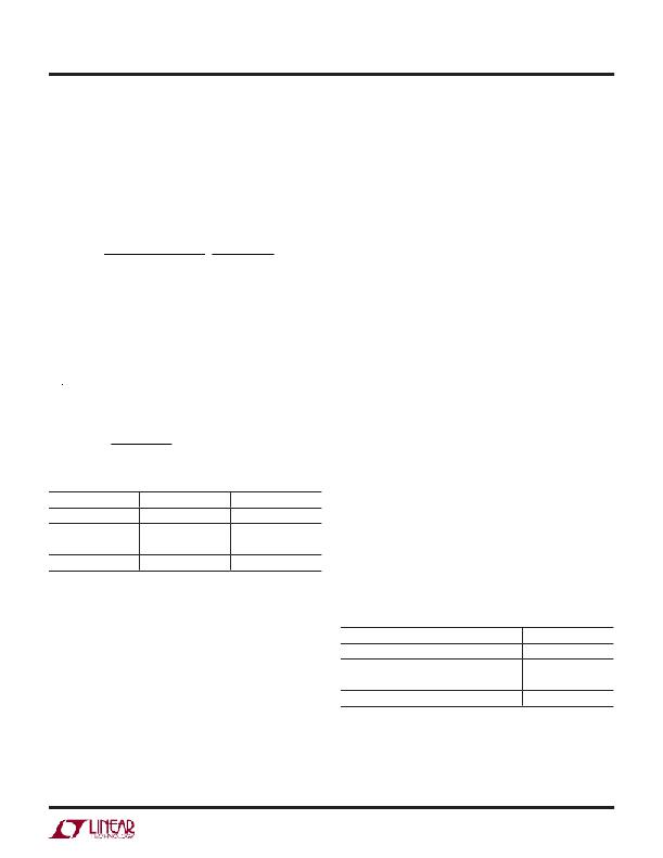
Table 1. Recommended Inductor Vendors
VENDOR PHONE
WEB
Use only ceramic capacitors with X7R, X5R or better dielec-
tric as they are best for temperature and DC bias stability
Sumida
Toko
Cooper
Vishay
(408)321-9660
(408)432-8281
(561)998-4100
(402)563-6866
www.sumida.com
www.toko.com
www.cooperet.com
www.vishay.com
of the capacitor value. All ceramic capacitors exhibit loss
of capacitance value with increasing DC voltage bias, so
it may be necessary to choose a higher value capacitor
to get the required capacitance at the operation voltage.
Input Capacitor Selection
For proper operation, it is necessary to place a bypass
capacitor to GND close to the V IN pin of the LT3519/
LT3519-1/LT3519-2. A 1μF or greater capacitor with low
Always check that the voltage rating of the capacitor is
suf?cient.
Table 2. Recommended Ceramic Capacitor Vendors
VENDOR PHONE WEB
ESR should be used. A ceramic capacitor is usually the
best choice.
In the buck mode con?guration, the capacitor at the input
to the power converter has large pulsed currents. For
TDK
Kemet
Murata
Taiyo Yuden
(516)535-2600
(408)986-0424
(814)237-1431
(408)573-4150
www.tdk.com
www.kemet.com
www.murata.com
www.t-yuden.com
best reliability, this capacitor should have low ESR and
3519fa
11
发布紧急采购,3分钟左右您将得到回复。
相关PDF资料
LT3590ESC8#TRMPBF
IC LED DRVR WHITE BCKLGT SC-70-8
LT3591EDDB#TRMPBF
IC LED DRIVER WHITE BCKLGT 8-DFN
LT3593ES6#TRMPBF
IC LED DRIVR WHITE BCKLGT TSOT-6
LT3595AEUHH#TRPBF
IC LED DRIVR WHITE BCKLGT 56-QFN
LT3595EUHH#TRPBF
IC LED DRIVR WHITE BCKLGT 56-QFN
LT3596EUHG#PBF
IC LED DVR 300MA ADJ 52-VQFN
LT3597EUHG#PBF
IC LED DRIVER TRPL STP DWN 52QFN
LT3598IUF#PBF
IC LED DRIVR WHITE BCKLGT 24-QFN
相关代理商/技术参数
LT3519EMS-2#PBF
制造商:Linear Technology 功能描述:IC LED DRIVER BOOST MSOP-16
LT3519EMS-2#TRPBF
功能描述:IC LED DRV HP CONST CURR 16MSOP RoHS:是 类别:集成电路 (IC) >> PMIC - LED 驱动器 系列:- 标准包装:6,000 系列:- 恒定电流:- 恒定电压:- 拓扑:开路漏极,PWM 输出数:4 内部驱动器:是 类型 - 主要:LED 闪烁器 类型 - 次要:- 频率:400kHz 电源电压:2.3 V ~ 5.5 V 输出电压:- 安装类型:表面贴装 封装/外壳:8-VFDFN 裸露焊盘 供应商设备封装:8-HVSON 包装:带卷 (TR) 工作温度:-40°C ~ 85°C 其它名称:935286881118PCA9553TK/02-TPCA9553TK/02-T-ND
LT3519EMSPBF
制造商:LINER 制造商全称:Linear Technology 功能描述:LED Driver with Integrated Schottky Diode
LT3519EMSTRPBF
制造商:LINER 制造商全称:Linear Technology 功能描述:LED Driver with Integrated Schottky Diode
LT3519IMS
制造商:LINER 制造商全称:Linear Technology 功能描述:LED Driver with Integrated Schottky Diode
LT3519IMS#PBF
功能描述:IC LED DRV HP CONST CURR 16MSOP RoHS:是 类别:集成电路 (IC) >> PMIC - LED 驱动器 系列:- 标准包装:6,000 系列:- 恒定电流:- 恒定电压:- 拓扑:开路漏极,PWM 输出数:4 内部驱动器:是 类型 - 主要:LED 闪烁器 类型 - 次要:- 频率:400kHz 电源电压:2.3 V ~ 5.5 V 输出电压:- 安装类型:表面贴装 封装/外壳:8-VFDFN 裸露焊盘 供应商设备封装:8-HVSON 包装:带卷 (TR) 工作温度:-40°C ~ 85°C 其它名称:935286881118PCA9553TK/02-TPCA9553TK/02-T-ND
LT3519IMS#TRPBF
功能描述:IC LED DRV HP CONST CURR 16MSOP RoHS:是 类别:集成电路 (IC) >> PMIC - LED 驱动器 系列:- 标准包装:6,000 系列:- 恒定电流:- 恒定电压:- 拓扑:开路漏极,PWM 输出数:4 内部驱动器:是 类型 - 主要:LED 闪烁器 类型 - 次要:- 频率:400kHz 电源电压:2.3 V ~ 5.5 V 输出电压:- 安装类型:表面贴装 封装/外壳:8-VFDFN 裸露焊盘 供应商设备封装:8-HVSON 包装:带卷 (TR) 工作温度:-40°C ~ 85°C 其它名称:935286881118PCA9553TK/02-TPCA9553TK/02-T-ND
LT3519IMS-1#PBF
功能描述:IC LED DRV HP CONST CURR 16MSOP RoHS:是 类别:集成电路 (IC) >> PMIC - LED 驱动器 系列:- 标准包装:6,000 系列:- 恒定电流:- 恒定电压:- 拓扑:开路漏极,PWM 输出数:4 内部驱动器:是 类型 - 主要:LED 闪烁器 类型 - 次要:- 频率:400kHz 电源电压:2.3 V ~ 5.5 V 输出电压:- 安装类型:表面贴装 封装/外壳:8-VFDFN 裸露焊盘 供应商设备封装:8-HVSON 包装:带卷 (TR) 工作温度:-40°C ~ 85°C 其它名称:935286881118PCA9553TK/02-TPCA9553TK/02-T-ND
